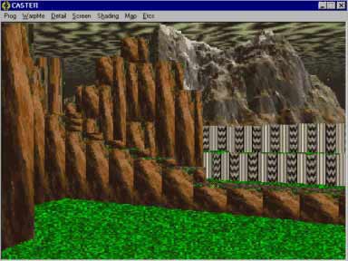
VARIABLE HEIGHT WALLSSo far, all the walls in our world have the same height. With some innovations, we can actually use walls of different height. This makes the world more interesting as illustrated in the next figure.
The easiest way to conceptualize variable height walls is to consider walls as floors. That is, imagine walls as floors that are raised. We will need an array to hold the height of each floor grid to make this work. The basic method to render the scene is this:
2. Find the height of the floor that the player is currently standing on. (Call this CURRENT_HEIGHT.) 3. Cast a ray and check intersections as before. 4. If the ray hits a floor that has different height than the CURRENT_HEIGHT, then that floor is either raised/sunk. (A raised floor is just a wall.) 5. If it is raised, then it will be visible. Project it, and render it. (Figure 30 below illustrates the math behind this.) 6. If it is sunk, then we don't need to project it because it will not be visible. 7. Draw the floor from the point of where the height changes occurs until the point where the top of the last wall slice is projected onto. (Initially, the top of last wall slice will be the bottom of the projection plane.) 8. Repeat until the ray extends pass the limit of the world map. 9. Repeat step 2 to 8 for all subsequent columns.
The main drawback of using variable height walls is that the rendering process will be considerably slower. This is because the rays no longer stops when the closest wall is hit. One way to speed this up is to set a visibility distance and simply ignore anything beyond that distance.
|
||